Category: Tutorial

  • Taming the Traffic Jungle: Wired and Wireless QoS Concepts for Enterprise Networks

    Taming the Traffic Jungle: Wired and Wireless QoS Concepts for Enterprise Networks

    Enterprise networks handle a wild mix of traffic—video calls, file transfers, cloud apps, and more—all competing for the same resources. Quality of Service (QoS) is the mechanism that brings order to this chaos, ensuring that critical applications get the performance they need.

    This blog breaks down the core concepts of QoS across both wired and wireless networks, explaining queuing, marking, policing, and shaping, and how policies drive traffic prioritization.


    Why QoS Matters in Enterprise Networks

    Without QoS, all traffic is treated equally—first come, first served. In peak hours, time-sensitive traffic like voice and video suffers, resulting in jitter, delay, or drops. QoS ensures that high-priority applications consistently perform well, even under congestion.


    Key Concepts

    1. Classification and Marking

    Classification identifies traffic types (e.g., voice, video, web), while marking tags packets so network devices can treat them accordingly.

    • Wired Networks: Use Layer 2 CoS (Class of Service) or Layer 3 DSCP (Differentiated Services Code Point) markings.
    • Wireless Networks: Mapping occurs between DSCP and wireless QoS profiles (WMM Access Categories).

    Example:

    • DSCP EF (Expedited Forwarding, value 46) is often used for voice.
    • DSCP AF41 is suitable for video conferencing.

    2. Queuing

    When traffic exceeds interface capacity, packets are placed in queues. Queuing mechanisms determine which packets are sent first.

    • FIFO (First-In, First-Out): No prioritization.
    • CBWFQ (Class-Based Weighted Fair Queuing): Allocates bandwidth per traffic class.
    • LLQ (Low Latency Queuing): Adds a strict-priority queue for delay-sensitive traffic like VoIP.

    3. Policing and Shaping

    Policing drops or re-marks excess traffic instantly; shaping buffers and sends it at a regulated rate.

    • Policing: Common on inbound traffic, ensuring users/applications don’t exceed allowed rates.
    • Shaping: Used outbound to smooth bursty traffic, often paired with queuing.

    4. Trust Boundaries

    Define where markings are accepted or rewritten. For example, in a wireless deployment, trust is usually given to the AP if it’s known to enforce QoS settings accurately.


    QoS in Wireless Networks

    Wireless adds extra complexity due to shared medium and variable transmission conditions.

    • WMM (Wi-Fi Multimedia) defines 4 Access Categories:
      • Voice (AC_VO)
      • Video (AC_VI)
      • Best Effort (AC_BE)
      • Background (AC_BK)

    APs translate DSCP into WMM categories, ensuring consistent QoS treatment end-to-end.

    Important: Congestion can occur on both the wired uplink and the wireless RF. QoS must be applied at both points.


    Policy-Driven QoS

    QoS policies use class maps, policy maps, and service policies in Cisco IOS.

    • Class Map: Matches traffic types.
    • Policy Map: Assigns QoS actions like bandwidth or marking.
    • Service Policy: Applies the policy to an interface.

    Config Insight: Simple LLQ for Voice Traffic

    class-map match-any VOICE
     match ip dscp ef
    
    policy-map QOS_POLICY
     class VOICE
      priority 1000
     class class-default
      fair-queue
    
    interface GigabitEthernet0/1
     service-policy output QOS_POLICY
    
  • Cisco SD-Access Architecture Explained: The Blueprint for Modern Campus Networks

    Cisco SD-Access Architecture Explained: The Blueprint for Modern Campus Networks

    As enterprise networks evolve, traditional campus architectures often struggle with increasing demands for automation, security, and scalability. Cisco Software-Defined Access (SD-Access) emerges as the answer—a network fabric that reimagines how campus networks are designed, deployed, and managed.

    This blog dives into the core concepts of SD-Access, focusing on its architecture, control and data planes, fabric overlays, and the coexistence strategy with traditional networks.


    Why SD-Access Is a Paradigm Shift

    Conventional campus designs rely heavily on manual configuration, VLAN sprawl, and inefficient access control methods. SD-Access simplifies these by abstracting the underlying network and introducing centralized policy, segmentation, and automation—all powered by Cisco DNA Center.


    Key Concepts

    SD-Access Architecture Overview

    At its core, SD-Access is a fabric-based network model where endpoints are decoupled from their physical locations. It introduces new roles and concepts:

    • Underlay: The foundational IP transport network (typically Layer 3), connecting all fabric nodes.
    • Overlay: The logical network built on top of the underlay, using tunneling (VXLAN) for segmentation and traffic forwarding.
    • Control Plane: A distributed database (LISP-based) that maps user/device identity to their current location.
    • Data Plane: VXLAN tunnels that forward encapsulated traffic across the fabric.

    Components of the SD-Access Fabric

    • Fabric Edge Nodes: Access-layer switches where endpoints connect; they encapsulate traffic into VXLAN.
    • Fabric Control Plane Node: Maintains endpoint location information using LISP; enables identity-based routing.
    • Fabric Border Node: Acts as the gateway between the SD-Access fabric and external networks (e.g., internet, non-fabric).
    • Fabric Wireless Controller: Integrates wireless traffic into the fabric using CAPWAP tunnels from access points.
    • DNA Center (DNAC): The central controller for policy, provisioning, and assurance in SD-Access.

    Control and Data Plane Deep Dive

    Control Plane (LISP – Locator/ID Separation Protocol)

    • Maintains a mapping database of Endpoint ID (EID) to Routing Locator (RLOC).
    • Enables seamless mobility—users can roam the network while retaining their IP and policy.

    Data Plane (VXLAN Tunneling)

    • Provides Layer 2 and Layer 3 segmentation via encapsulated traffic.
    • Supports scalable group segmentation (SGT) for enforcing policies between different user or device groups.

    Overlay Fabric Communication

    • When an endpoint connects, the fabric edge node queries the control plane for the destination location.
    • Once located, a VXLAN tunnel is built dynamically to the corresponding fabric node for traffic forwarding.

    Traditional Campus Network Integration

    SD-Access does not demand a rip-and-replace strategy. It can coexist with traditional campus networks:

    • Via Border Nodes: The SD-Access fabric connects to legacy Layer 2/Layer 3 domains through the border node, preserving interoperability.
    • Shared Services: DNS, DHCP, or internet access can reside outside the fabric but be accessible through policies.
    • Staging Migration: Organizations can transition floor-by-floor or building-by-building to SD-Access.

    Considerations for Design and Deployment

    • Underlay Design: Ensure reliable IP connectivity—often using IS-IS or OSPF.
    • Control Plane Redundancy: Deploy multiple control nodes for high availability.
    • Segmentation Strategy: Plan VRFs and SGTs early to align with business groups.
    • Wireless Integration: Use Fabric Mode WLCs and APs to fully extend the fabric to wireless clients.
    • Monitoring: Leverage DNA Center Assurance for deep insights and anomaly detection.

    Config Insight: Verifying VXLAN Tunnel on Edge Node

    show fabric vn-segment
    

    This command provides information about VXLAN tunnels and segment IDs on Cisco fabric-enabled switches.

  • Traditional WAN vs. SD-WAN: A Tale of Two Architectures

    Traditional WAN vs. SD-WAN: A Tale of Two Architectures

    The way enterprises connect remote branches to their data centers and applications has dramatically changed. Traditional WANs served well in the era of centralized computing, but as cloud adoption surged, so did the need for a more agile, scalable, and cost-effective solution—enter SD-WAN.


    The WAN Evolution

    Traditional WANs relied heavily on private circuits like MPLS for site-to-site connectivity. These networks were dependable but expensive, with limited flexibility. Modern businesses now need dynamic access to cloud applications, SaaS platforms, and hybrid environments—all with predictable performance and security.


    Key Concepts

    Traditional WAN

    • Architecture: Hub-and-spoke, where branch offices connect to a central data center via MPLS.
    • Routing: Static or manually configured routing policies.
    • Traffic Flow: All branch internet traffic is typically backhauled to the data center.
    • Management: Device-by-device configuration, often requiring on-site IT support.
    • Security: Centralized at the data center, with firewalls and security stacks.

    Limitations:

    • Costly MPLS circuits
    • Poor cloud performance due to backhaul
    • Limited visibility and control
    • Complex provisioning and scaling

    Software-Defined WAN (SD-WAN)

    • Architecture: Cloud-first, with direct-to-internet and inter-branch IPsec tunnels.
    • Routing: Centralized policy-driven routing via controllers like Cisco vSmart.
    • Traffic Flow: Internet-bound traffic can exit directly from the branch (DIA).
    • Management: Centralized via GUI dashboards (e.g., Cisco vManage).
    • Security: Integrated or cloud-based, with encryption, firewall, and segmentation.

    Advantages:

    • Cost savings through broadband and LTE use
    • Improved cloud access and application performance
    • Simplified provisioning with zero-touch deployment
    • Granular control with application-aware policies

    Side-by-Side Comparison

    FeatureTraditional WANSD-WAN
    TransportPrimarily MPLSMPLS, Broadband, LTE
    ArchitectureHub-and-SpokeCloud-Optimized, Any-to-Any
    SecurityCentralizedDistributed and Integrated
    Traffic HandlingBackhauledDirect Internet Access (DIA)
    ProvisioningManual, ComplexZero-Touch Provisioning (ZTP)
    Policy ControlStaticCentralized and Dynamic
    Cloud IntegrationLimitedNative and Optimized

    Considerations for Migration

    • Business Goals: Cost reduction, cloud readiness, remote work?
    • Network Size: Number of branches, cloud dependencies.
    • Security Needs: Compliance, segmentation, threat protection.
    • IT Skillset: Comfort with centralized management and automation.

    Config Insight: SD-WAN Tunnel Verification

    show sdwan control connections

    This command checks the control plane tunnel status on a Cisco SD-WAN edge device.

  • Behind the Scenes of Cisco SD-WAN: Control and Data Planes Demystified

    Behind the Scenes of Cisco SD-WAN: Control and Data Planes Demystified

    Software-Defined WAN (SD-WAN) is revolutionizing how enterprises connect distributed sites, ensuring performance, security, and flexibility across various transport networks like MPLS, broadband, and LTE. Cisco’s SD-WAN solution goes a step further—integrating cloud-first architecture with enterprise-grade security and centralized control.


    Why Cisco SD-WAN Is a Game-Changer

    Traditional WANs are rigid and expensive to scale. Cisco SD-WAN separates control from data forwarding, enabling intelligent routing, simplified management, and secure connectivity—even across the public internet. It’s like upgrading from a paper map to a GPS with traffic-aware rerouting.


    Key Concepts

    Control Plane vs. Data Plane

    • Control Plane: Manages routing decisions, topology awareness, and policy enforcement.
    • Data Plane: Handles the actual forwarding of user traffic between sites.

    In Cisco SD-WAN, these planes are separated and handled by different elements:


    SD-WAN Components and Their Roles

    1. vSmart Controller (Control Plane)

    • Acts as the policy and routing brain of the SD-WAN fabric.
    • Distributes control and security policies to WAN edge devices.
    • Uses secure connections (DTLS/TLS) to communicate with edge devices.

    2. vBond Orchestrator (Authentication and Orchestration)

    • The first point of contact for all SD-WAN components.
    • Authenticates WAN edge devices (using certificates) and helps them discover vSmart and vManage.
    • Ensures proper NAT traversal for devices behind firewalls.

    3. vManage NMS (Network Management System)

    • Central GUI dashboard for configuration, monitoring, and troubleshooting.
    • Pushes configurations and policies to all SD-WAN devices.
    • Supports zero-touch provisioning (ZTP).

    4. WAN Edge Routers (Data Plane)

    • Also called Cisco SD-WAN routers or vEdge/Catalyst Edge.
    • Forward traffic based on policies and topology from the vSmart controller.
    • Build secure IPsec tunnels with other edge devices.

    How It All Works Together

    1. Device Onboarding: WAN edge devices authenticate via vBond and register with vManage and vSmart.
    2. Policy Distribution: vSmart pushes control and data policies to the WAN edge routers.
    3. Tunnel Formation: Edge devices establish IPsec tunnels with each other using information from vSmart.
    4. Traffic Forwarding: Data flows directly between sites using the optimal path as determined by policy.

    Considerations for Design

    • Redundancy: Deploy multiple controllers (vSmart, vBond, vManage) for HA.
    • Scalability: Cloud-hosted controllers scale easily with enterprise growth.
    • Security: End-to-end encryption via IPsec tunnels.
    • Cloud Integration: Direct connections to SaaS/IaaS platforms using Cloud OnRamp.

    Config Insight: vEdge Control Connection Verification

    vEdge# show control connections

    This command confirms if the vEdge router is securely connected to vSmart and vBond controllers.

  • Pinpointing Precision: Understanding Location Services in WLAN Design

    Pinpointing Precision: Understanding Location Services in WLAN Design

    Wi-Fi is no longer just about internet access—it’s about intelligence. Modern wireless LANs (WLANs) do more than connect devices; they can track their location. Location services have become a powerful tool in environments like healthcare, retail, manufacturing, and even smart campuses, providing insights into movement, usage, and security.


    Why Location Services Matter

    Knowing where a device is within a building can improve safety, enhance customer experience, and streamline operations. From tracking assets in hospitals to pushing promotions in retail stores, WLAN-based location services unlock a new layer of network value.


    Key Concepts

    1. Types of WLAN Location Services

    • Presence: Detects if a device is in the area—basic, but useful for foot traffic analysis.
    • Zone-Based Location: Identifies general areas or zones where a device is located (e.g., lobby, office).
    • XY Location (Real-Time Location Services or RTLS): Tracks exact coordinates within a space.
    • Z-Axis (Vertical Positioning): Determines floor level in multistory buildings.

    2. Technologies Behind Location Services

    • RSSI (Received Signal Strength Indicator): Measures signal strength from APs to estimate proximity. Simple but affected by walls and interference.
    • TDoA (Time Difference of Arrival): Measures time for signals to reach multiple APs to triangulate position. More accurate but requires tight synchronization.
    • Angle of Arrival (AoA): Uses antenna arrays to calculate direction of the signal. High precision in newer deployments.
    • BLE (Bluetooth Low Energy): Often used in conjunction with Wi-Fi for hyperlocal accuracy.

    3. Location Engines and Platforms

    • Cisco DNA Spaces: Offers presence analytics, location heat maps, behavior patterns, and integration with business applications.
    • Cisco CMX (Connected Mobile Experiences): Legacy platform for location tracking and analytics.

    Considerations for WLAN Location Design

    • Access Point Density: Minimum of 3 APs in range for accurate triangulation.
    • AP Placement: Uniform spacing and low mounting height improve precision.
    • Calibration: Perform RF fingerprinting for higher accuracy, especially in RTLS.
    • Device Type Awareness: Different devices report RSSI differently—consider in tuning.
    • Privacy and Compliance: Implement policies that align with data protection regulations.

    Config Insight: Enabling Location Services on a Cisco WLC

    wlc# config location enable
    wlc# config location history enable

    Note: Advanced location features typically require integration with Cisco DNA Spaces or CMX.

  • Choosing the Right Wireless Deployment Model: Centralized, Distributed, Cloud, and More

    Choosing the Right Wireless Deployment Model: Centralized, Distributed, Cloud, and More

    Wireless networks are no longer optional—they’re essential. But not all wireless setups are created equal. Depending on the size, location, and goals of a business, the right deployment model can drastically improve performance, manageability, and scalability. Understanding the strengths and use cases of different wireless deployment models is key to designing a robust network.


    Why Wireless Deployment Models Matter

    Selecting the wrong wireless architecture can lead to poor coverage, scalability issues, and difficult management. A proper model ensures better performance, centralized control, and optimized costs based on the organization’s needs.


    Key Concepts

    Centralized (Controller-Based) Deployment
    All access points (APs) forward traffic and control functions to a central Wireless LAN Controller (WLC). The WLC manages configurations, security, and policies.

    • Ideal for: Medium to large campus networks
    • Benefits: Centralized management, scalability, policy consistency
    • Drawback: Controller is a single point of failure without redundancy

    Distributed (Autonomous) Deployment
    Each AP operates independently, making its own decisions and handling management and data forwarding locally.

    • Ideal for: Small offices or isolated deployments
    • Benefits: Simple setup, no need for central controller
    • Drawback: Difficult to manage at scale, lacks centralized control

    Controller-Less (Mobility Express or Embedded WLC)
    An AP takes on the role of a controller for a small group of APs, combining the benefits of centralized and autonomous deployments.

    • Ideal for: Small to mid-sized businesses
    • Benefits: Centralized-like management without dedicated WLC
    • Drawback: Limited scalability

    Cloud-Based Deployment
    APs connect to a cloud-managed platform (e.g., Cisco Meraki), which handles configuration, monitoring, and updates.

    • Ideal for: Multi-site businesses, retail chains
    • Benefits: Easy remote management, reduced on-site IT needs
    • Drawback: Requires reliable internet connectivity

    Remote Branch Deployment
    Designed for branch offices connected to a central hub, often using FlexConnect or SD-Branch solutions. Local switching is available even if WAN fails.

    • Ideal for: Branch offices with limited IT resources
    • Benefits: Central control, local resiliency
    • Drawback: Complex WAN dependency if not configured properly

    Considerations When Choosing a Model

    • Scale: How many APs and locations are needed?
    • Control: Is centralized management essential?
    • Resiliency: What happens during WAN outages?
    • IT Resources: Is there staff available for on-site management?
    • Cost: Budget for hardware, licenses, and ongoing support

    Config Insight: Basic AP Registration with Controller

    AP# capwap ap controller ip address 192.168.100.10

  • Never Down Again: Mastering High Availability with Redundancy, FHRP, and SSO

    Never Down Again: Mastering High Availability with Redundancy, FHRP, and SSO

    Downtime is the nemesis of modern enterprise networks. Whether it’s caused by hardware failure, software bugs, or human error, even a few minutes of network outage can disrupt operations and cost businesses real money. High availability (HA) techniques aim to eliminate single points of failure and ensure uninterrupted network services.


    What Makes a Network “Highly Available”?

    High availability doesn’t just mean having extra equipment—it’s about designing the network so that if one component fails, others can instantly take over without disruption. This is done using a combination of physical and logical redundancy, failover protocols, and software enhancements.


    Key Concepts

    Redundancy
    Redundancy involves deploying duplicate network elements—like routers, switches, links, and power supplies—to serve as backups in case of failure.

    • Link Redundancy: Multiple uplinks prevent isolation of network segments.
    • Device Redundancy: Backup routers or switches ensure uninterrupted routing and switching.
    • Path Redundancy: Multiple data paths maintain connectivity if one route fails.

    First Hop Redundancy Protocol (FHRP)
    End devices rely on a default gateway for outbound traffic. If that gateway fails, without FHRP, traffic halts. FHRP introduces a virtual IP address shared between two or more routers.

    • HSRP (Hot Standby Router Protocol) – Cisco proprietary, uses an active/standby model.
    • VRRP (Virtual Router Redundancy Protocol) – Open standard, similar to HSRP.
    • GLBP (Gateway Load Balancing Protocol) – Cisco proprietary, offers load balancing and redundancy.

    Stateful Switchover (SSO)
    SSO enables a router or switch with dual route processors to seamlessly switch from a failed active processor to a standby one without interrupting traffic.

    • Function: Synchronizes configuration and forwarding information between processors.
    • Use Case: Most effective in modular switches and high-end routers with redundant supervisors.

    Considerations for Implementing High Availability

    • Critical Path Identification: Focus HA designs on links and devices that handle essential traffic.
    • Failover Time: Minimize downtime by using fast convergence protocols and SSO.
    • Load Sharing: Where possible, use GLBP or similar methods to balance traffic across redundant paths.
    • Cost vs. Benefit: High availability often requires more hardware—ensure it aligns with business impact and budget.
    • Maintenance: Plan for software upgrades and changes without full network outages.

    Config Sample: HSRP Basic Setup

    interface GigabitEthernet0/1
     ip address 192.168.10.2 255.255.255.0
     standby 1 ip 192.168.10.1
     standby 1 priority 110
     standby 1 preempt
  • Mastering Enterprise Network Design: Tier 2, Tier 3, and Fabric Capacity Planning

    Mastering Enterprise Network Design: Tier 2, Tier 3, and Fabric Capacity Planning

    When businesses scale up, their network infrastructure must evolve just as quickly. A simple flat network might work for a startup, but it often crumbles under the weight of growing user demands, applications, and devices. This is where structured enterprise network designs—Tier 2, Tier 3, and Fabric—play a crucial role, along with proactive capacity planning.


    Why Network Design Matters

    Enterprise networks, much like urban road systems, need thoughtful planning to handle growing traffic. A well-architected network improves performance, supports scalability, ensures reliability, and makes troubleshooting significantly easier. Without a clear design, bottlenecks and outages can quickly disrupt operations.


    Understanding Tier 2, Tier 3, and Fabric Designs

    Tier 2 (Collapsed Core Architecture):
    Ideal for small to medium enterprises, this design merges the core and distribution layers into one. It’s simple and cost-effective, reducing the number of devices and overall complexity.

    • Strengths: Lower cost, easier deployment and management.
    • Limitations: Less redundancy, scalability constraints.

    Tier 3 (Traditional Hierarchical Design):
    Best suited for larger networks, this model divides the architecture into three layers: Access, Distribution, and Core.

    • Access Layer: Connects end-user devices to the network.
    • Distribution Layer: Aggregates traffic and enforces policies.
    • Core Layer: High-speed backbone that connects distribution layers.
    • Strengths: Excellent scalability, fault tolerance, and modularity.
    • Limitations: Higher infrastructure and maintenance costs.

    Fabric Design (Software-Defined Access – SD-Access):
    The most modern approach, fabric-based architecture virtualizes the network and introduces automation and centralized management.

    • Strengths: Policy consistency, segmentation, scalability, automation.
    • Limitations: Requires deeper expertise and investment.

    Key Considerations for Capacity Planning

    Effective capacity planning ensures the network can support both current demands and future growth. Poor planning often leads to bandwidth shortages, hardware strain, and user dissatisfaction.

    • Growth Forecasting: Estimate future users, devices, and application needs.
    • Traffic Analysis: Account for peak usage periods, not just daily averages.
    • Redundancy: Implement failover options at critical points.
    • Uplink Optimization: Ensure trunk links can handle aggregate traffic.
    • Physical Resources: Consider power, space, and cooling needs.
    • Scalability: Choose equipment and topologies that allow for easy expansion.

    Config Sample: Setting Up VLAN Access and Trunk Ports

    interface FastEthernet0/1
     switchport mode access
     switchport access vlan 10
     spanning-tree portfast
    
    interface GigabitEthernet0/1
     switchport trunk encapsulation dot1q
     switchport mode trunk
  • Spanning Tree Protocol (STP)

    Spanning Tree Protocol (STP)

    In Ethernet networks, redundant paths are often introduced to ensure high availability and fault tolerance. However, redundancy at Layer 2 creates a serious problem: switching loops. When loops occur, frames can circulate endlessly, consuming bandwidth and degrading network performance.

    The Spanning Tree Protocol (STP), defined in IEEE 802.1D, is designed to solve this problem. It does so by dynamically creating a loop-free logical topology, even if physical loops exist. STP identifies redundant links and places them into a blocking state while keeping one active path between switches. If the active path fails, STP recalculates and unblocks a previously redundant link to maintain connectivity.

    Over time, enhancements have been made to improve STP convergence and functionality, leading to variants like Rapid Spanning Tree Protocol (RSTP – IEEE 802.1w) and Multiple Spanning Tree Protocol (MSTP – IEEE 802.1s).


    Why Is STP Important?

    Without STP or a similar loop prevention mechanism, Layer 2 networks can quickly become unusable due to broadcast storms, MAC address table instability, and multiple frame copies.

    Here’s why STP is critical in enterprise environments:

    • Network Stability: Prevents endless loops that can bring down the entire LAN.
    • High Availability: Allows redundant links to exist without disrupting the network.
    • Automatic Recovery: Detects link failures and recalculates the topology to restore connectivity.
    • Scalability: Ensures that as networks grow and more switches are added, loops are avoided without manual intervention.

    Practical Use Cases

    1. Enterprise Campus Networks:
      Large networks typically have redundant links between access, distribution, and core layers. STP ensures that traffic follows a loop-free path while keeping backup links ready for failover.
    2. Data Centers:
      In environments requiring high availability and uptime, STP prevents loops and ensures quick recovery when a primary link goes down.
    3. Branch Offices with Redundant WAN Links:
      Although Layer 3 routing handles WAN redundancy, local LANs still rely on STP to manage multiple paths to critical resources like servers or internet gateways.
    4. Network Maintenance Scenarios:
      When performing planned maintenance, STP allows network engineers to temporarily disable certain links without affecting network availability, knowing STP will recalculate the best available path.

    Related Technologies and Protocols

    1. Rapid Spanning Tree Protocol (RSTP – IEEE 802.1w)
      RSTP is an evolution of classic STP, offering faster convergence. While traditional STP might take 30-50 seconds to reconverge after a topology change, RSTP typically achieves convergence within seconds. It introduces new port roles (Alternate, Backup) and port states (Discarding, Learning, Forwarding).
    2. Multiple Spanning Tree Protocol (MSTP – IEEE 802.1s)
      MSTP allows multiple VLANs to share a single spanning tree instance, reducing the processing overhead and improving load balancing across redundant links. This is highly beneficial in large-scale enterprise networks with many VLANs.
    3. Per-VLAN Spanning Tree Plus (PVST+)
      Cisco’s proprietary enhancement that runs a separate STP instance for each VLAN. This allows load balancing by forwarding different VLANs over different physical paths.
    4. Rapid PVST+
      Combines the benefits of RSTP with per-VLAN control. It is widely used in Cisco networks for faster convergence while still allowing fine-grained control per VLAN.
    5. BPDU Guard and BPDU Filter
      These security mechanisms prevent STP manipulation by disabling ports that receive unexpected Bridge Protocol Data Units (BPDUs). Often used on access ports to prevent rogue switches from participating in STP.

    Essential Cisco IOS Commands to Remember

    1. Verify STP Status

    show spanning-tree
    show spanning-tree vlan <vlan_id>

    2. Manually Set the Root Bridge Priority

    configure terminal
    spanning-tree vlan <vlan_id> priority <value>

    Lower priority values make a switch more likely to become the root bridge (default is 32768).

    3. Enable PortFast on Access Ports (Prevents STP Delays)

    interface <interface_id>
    spanning-tree portfast

    4. Enable BPDU Guard (Protect Against Rogue Switches)

    interface <interface_id>
    spanning-tree bpduguard enable

    5. Enable BPDU Filter (Suppress BPDU Transmission and Reception)

    interface <interface_id>
    spanning-tree bpdufilter enable

    6. Change Path Cost or Port Priority (For Tuning Traffic Paths)

    interface <interface_id>
    spanning-tree vlan <vlan_id> cost <value>
    spanning-tree vlan <vlan_id> port-priority <value>

    7. Check Which Switch is the Root Bridge

    show spanning-tree root

    8. View STP Topology Changes

    show spanning-tree detail

    Summary

    Understanding and configuring STP and its related technologies is critical for maintaining a resilient and stable Layer 2 infrastructure. Cisco IOS provides the necessary tools to fine-tune spanning tree behavior, improve convergence times, secure the network from unintended topology changes, and optimize traffic flow.

  • Packet Forwarding

    Packet Forwarding

    Packet forwarding is the invisible force that keeps the digital world connected. Every time you browse a website, send an email, or attend a video call, packets—tiny units of data—are being forwarded across networks to deliver your content. In the simplest sense, packet forwarding is the process of moving these packets from one network device to another until they reach their destination. But beneath this simplicity lies a sophisticated mechanism that ensures data travels efficiently and securely, especially in today’s complex enterprise environments.

    Why Should You Care About Packet Forwarding?

    If you’re working with networks, packet forwarding is a concept you cannot ignore. It’s at the heart of ensuring reliable communication within and between networks. Poorly configured forwarding leads to slow networks, bottlenecks, and even security vulnerabilities. Understanding how packets find their way through a network enables you to design faster, more resilient, and secure infrastructures. Whether you’re optimizing performance for a data center or simply troubleshooting a slow office network, knowing how forwarding works is essential.


    Layer 2 vs. Layer 3 Forwarding – When and Why Each Matters

    In smaller networks or within a local environment, devices communicate using Layer 2 forwarding. Think about an office with computers connected to a single switch. Here, devices identify each other by MAC addresses, and the switch is responsible for directing packets internally. This method is fast and efficient for local communication but fails when devices need to talk to other networks.

    That’s where Layer 3 forwarding, or routing, becomes crucial. When data needs to leave the local network—perhaps to access the internet or reach a server in another branch—routers come into play. These devices work with IP addresses and make decisions based on routing tables, determining the best path for data to travel across networks.

    Let’s take a practical example. Imagine a company with separate networks for its Finance and HR departments. Although both departments are in the same building, their networks are segmented for security reasons. A Layer 3 device is needed to allow selective communication between these networks while enforcing access controls. Without this, the Finance department wouldn’t be able to securely access a central accounting application hosted on a different subnet.


    How Does Packet Forwarding Actually Happen?

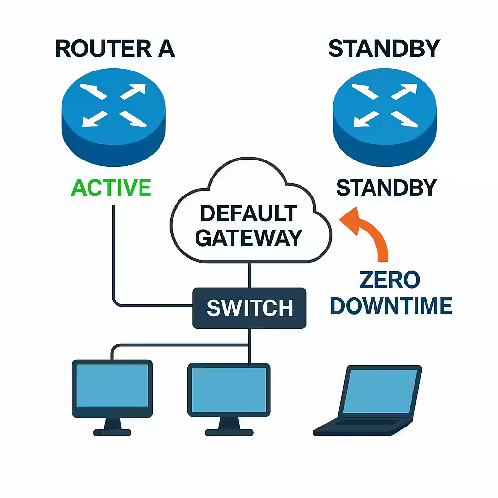
    When a device sends data, it first tries to determine if the destination is within its own network. If it is, the switch forwards the packet directly based on the MAC address. If not, the packet is sent to the default gateway—a router—which then decides where to forward it next.

    Modern routers and switches rely on advanced techniques like Cisco Express Forwarding (CEF) to make these decisions quickly. CEF uses special data structures called the Forwarding Information Base (FIB) and adjacency tables to make lightning-fast forwarding decisions. This ensures that even in large-scale environments like data centers or cloud infrastructures, packet forwarding happens with minimal delay.


    Real-World Impact of Efficient Packet Forwarding

    In high-demand environments such as financial institutions, milliseconds of delay can result in massive financial losses. Similarly, in healthcare, the speed and reliability of packet forwarding can directly impact critical services like remote diagnostics and real-time patient monitoring.

    From a business perspective, faster packet forwarding means smoother video conferences, quicker access to cloud applications, and better overall user satisfaction. It also means that network hardware is used efficiently, reducing the need for costly upgrades.


    Technologies Related to Packet Forwarding

    1. Cisco Express Forwarding (CEF)

    CEF is the cornerstone of modern Cisco packet forwarding. It addresses the need for faster packet processing by avoiding repetitive lookups in the routing table. Instead, CEF pre-builds two critical data structures:

    • FIB (Forwarding Information Base): This contains the best-known routes derived from the routing table.
    • Adjacency Table: This stores Layer 2 next-hop information to ensure quick MAC address resolution.

    With these tables ready in memory, routers and switches can make forwarding decisions almost instantly. CEF is enabled by default on most modern Cisco platforms and is especially critical in high-speed environments such as data centers and large campuses.

    Verification Command:

    show cef

    2. Distributed Forwarding (dCEF)

    In high-performance devices like the Cisco Catalyst 9500 series or Nexus data center switches, forwarding decisions can be offloaded from the main CPU to dedicated line cards. This is known as distributed forwarding or dCEF.

    Each line card maintains its own copy of the FIB and adjacency tables, allowing packets to be processed locally on the line card without burdening the central processor. This is essential for achieving low latency and high throughput in enterprise and service provider networks.


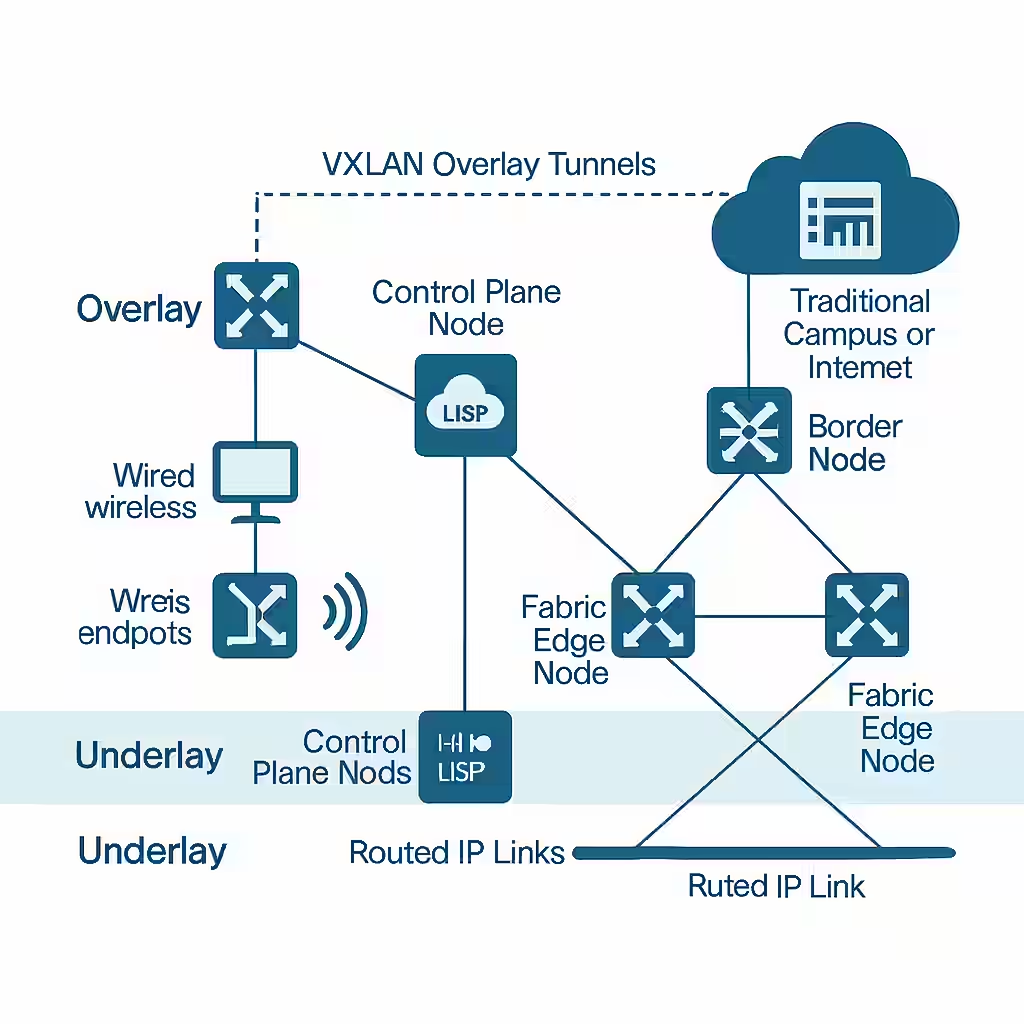
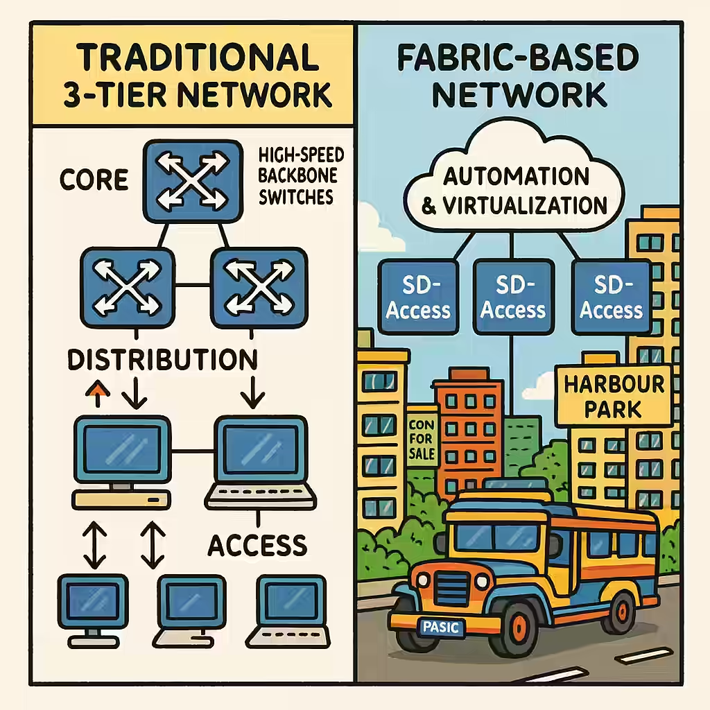
    3. Software-Defined Access (SD-Access)

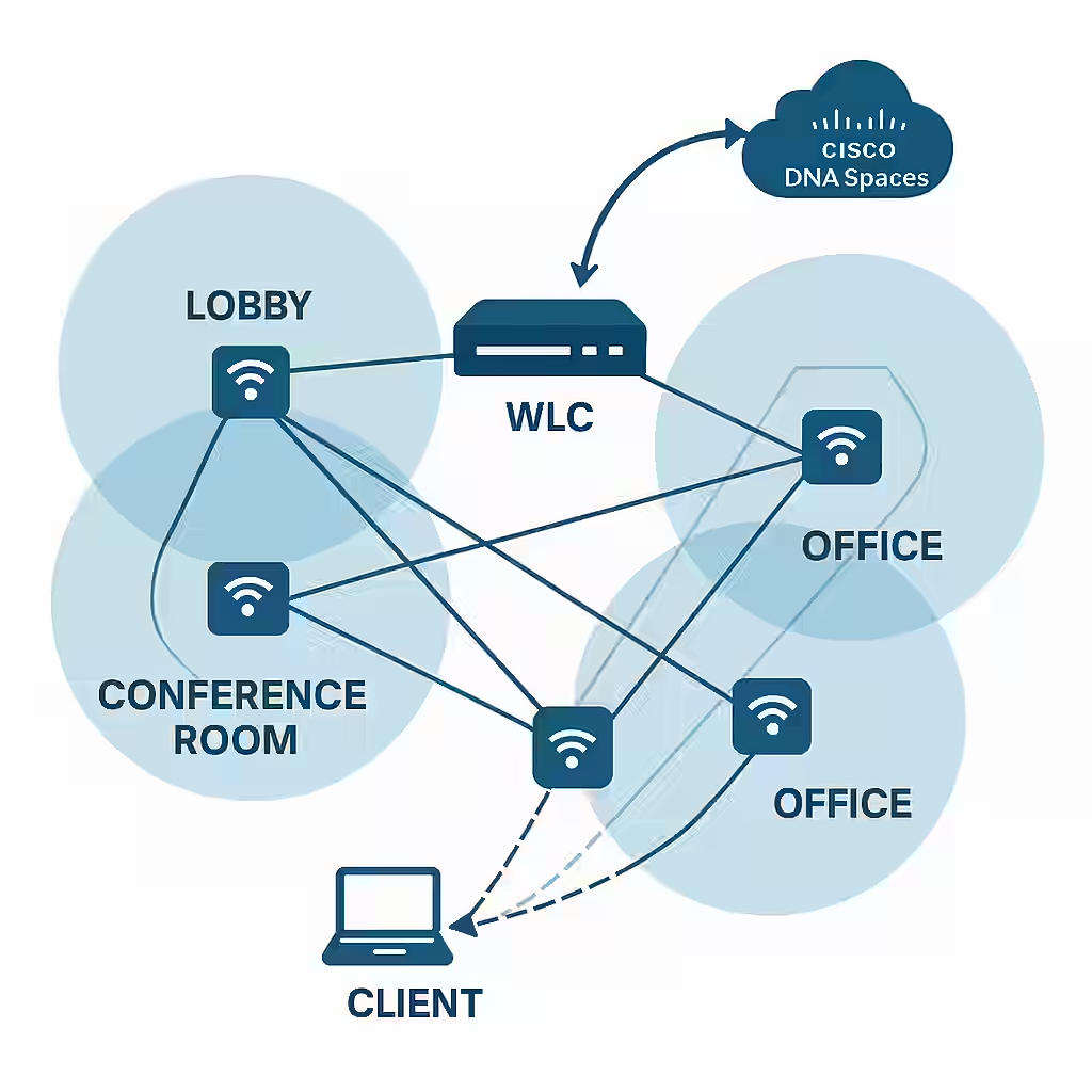
    Cisco SD-Access introduces a modern way of handling packet forwarding through fabric-based architectures. Using the LISP (Locator/ID Separation Protocol), it separates device identity from location, allowing seamless mobility and simplified policy enforcement.

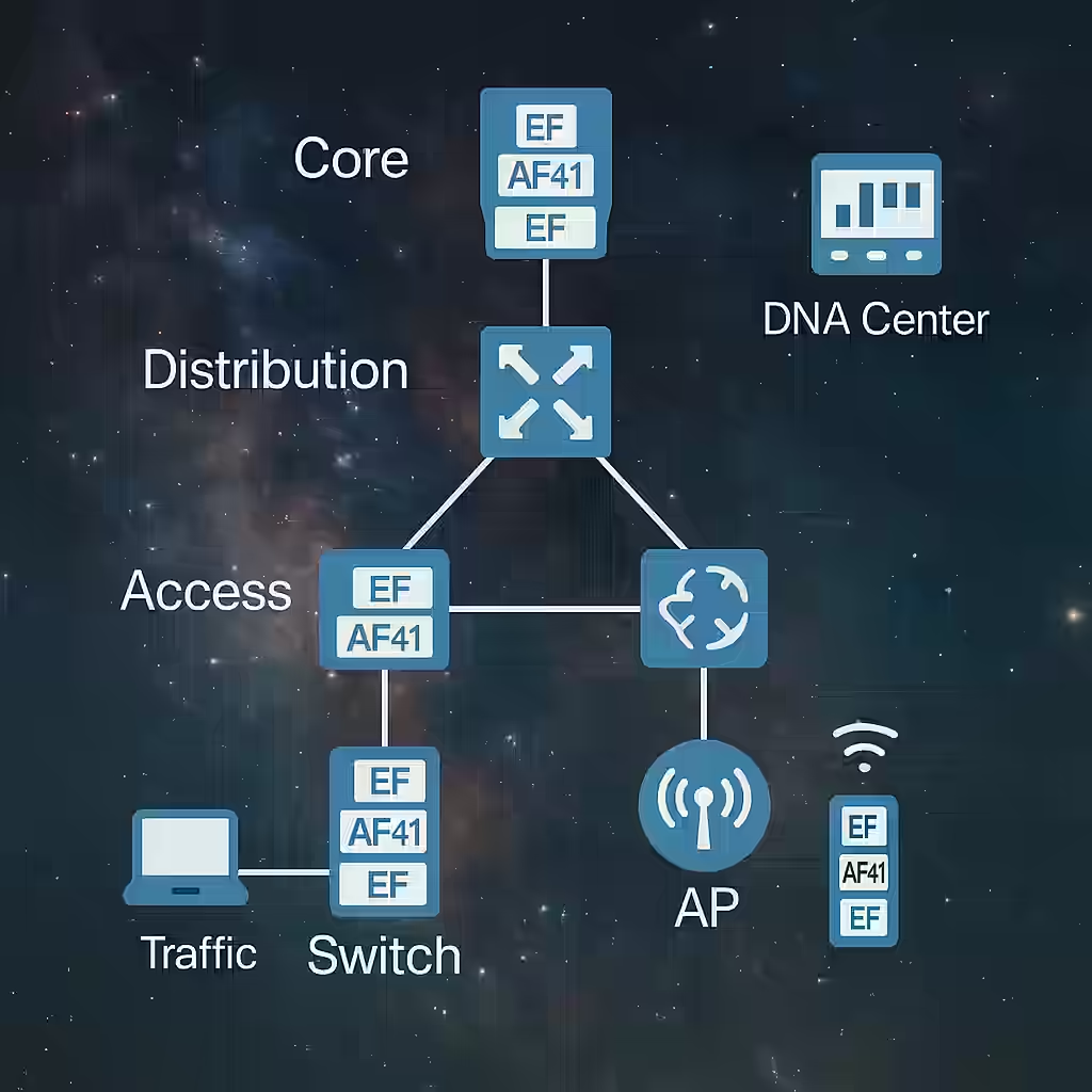
    In SD-Access environments, forwarding decisions aren’t made solely by analyzing IP and MAC addresses. Instead, they consider user identity, device type, and security policies, which are centrally managed by Cisco DNA Center.

    Key Technologies Used:

    • LISP for identity-based routing.
    • VXLAN for network virtualization and encapsulating traffic between fabric nodes.

    4. Virtual Extensible LAN (VXLAN)

    VXLAN is a technology that supports large-scale Layer 2 networks over a Layer 3 infrastructure. In packet forwarding, VXLAN plays a key role in environments requiring network virtualization—common in data centers and cloud networks.

    Cisco devices like the Nexus 9000 series utilize VXLAN to encapsulate Layer 2 frames within Layer 3 packets, allowing for scalable and efficient forwarding across distributed environments.


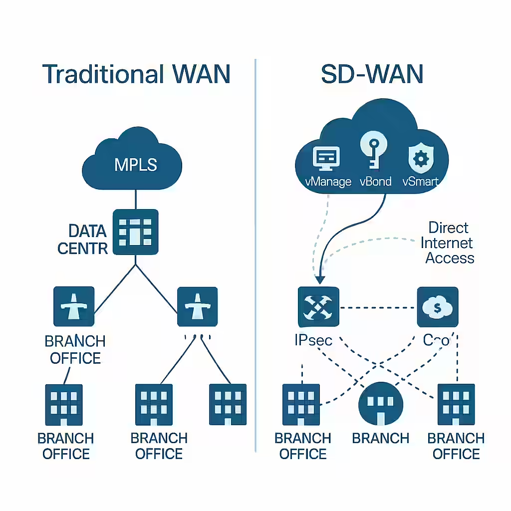
    5. Cisco SD-WAN (Software-Defined WAN)

    In WAN environments, Cisco’s SD-WAN solution changes how packets are forwarded between branch offices, data centers, and cloud services. Instead of static routing decisions, SD-WAN uses policies defined by business intent.

    The SD-WAN fabric dynamically chooses the best path for packets based on real-time conditions like latency, jitter, and packet loss. It uses intelligent controllers (vSmart and vBond) to enforce these decisions, improving application performance over less expensive internet circuits.


    6. Quality of Service (QoS) in Forwarding

    Cisco integrates QoS mechanisms directly into the packet forwarding process. When forwarding packets, especially in congested environments, devices prioritize traffic based on QoS policies. This ensures critical applications such as VoIP and video conferencing receive the necessary bandwidth and low latency, even under heavy network load.

    Verification Command:

    show policy-map interface

    7. Forwarding Hardware Acceleration (ASICs)

    Cisco’s custom-designed Application-Specific Integrated Circuits (ASICs), like the UADP (Unified Access Data Plane) and Cisco Silicon One, are purpose-built to accelerate packet forwarding at the hardware level. These chips allow for massive packet throughput without relying on software-based decision-making, making them ideal for core routers and high-performance switches.


    Conclusion

    Packet forwarding is more than a background process; it’s the backbone of network communication. Whether you’re a network engineer, a system administrator, or simply someone curious about how networks operate, understanding packet forwarding helps you see the bigger picture of how devices communicate, how traffic is controlled, and how performance is optimized.